User Manual
Power
Different VTXs have different power requirements, please refer to the target for detial.
Led
All VTXes have two LEDs
RED LED
power indicator light.
The VTX lights up when powered on and goes off when powered off. It will not flash.
BLUE LED
Working status indicator light.
- Flicker 3x after boot indicates MSP signaling is detected.
- Specific modes are represented with patterns of long (1 seconds) and short (1/4 seconds) pulses, within a 4 seconds timeframe
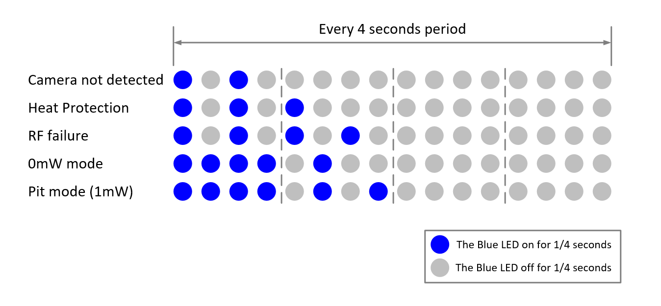
Note the first three in the list, are error cases and are checked ahead of any others, and will be displayed if in force. This means for example, that if the vtx is in heat protection mode, setting the board to 0mW will not be apparent.
Keypad
Note not all VTXes support keypad.
UART
- VTX is connected to FC through UART to implement OSD and other functions that require remote control cooperation.
- Do not use soft serial uart.
- VTX TX <=> FC RX
- VTX RX <=> FC TX
Baud rate
VTX supports two baud rates: 115200 and 230400.
Note: HDZero Race V3 VTX only support 115200 baud rate.
During the initialization phase, VTX will detect whether the serial port can correctly receive osd data. If the correct osd data packet is not received for more than 2 seconds, VTX will automatically switch the baud rate.
OSD setup
Prerequisition
- Betaflight >= v4.4.0
- iNav >= 4.1.0
- FlightOne >= 10.1.1.5576 | 10.1 Alpha 29
Update VTX and VRX/Goggle firmware
- Download the latest firmware from www.hd-zero.com/document.
- Firmware package(Rev_ddmmyyyy.zip) contains the firmware for all the VTX and VRX/Goggle.
- You can also get the latest release fw of vtx and goggle from github.
Solder/Connect UART to and available on your FC board
See UART abve.
Flight Controller Configuration(Use betaflight as example)
- Connect the FC board to computer with an USB cable
- Start Betaflight Configurator
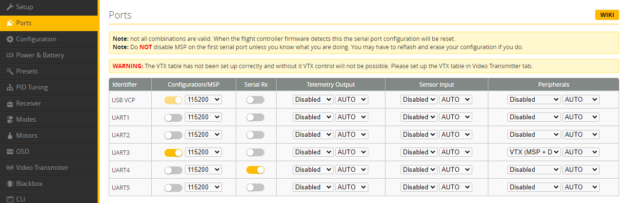
- Go to Port TAB
- Activite VTX (MSP + Displayport) on UART number that is used to connect the VTX
- Save and Reboot
Note: A soft UART is not supported for VTX (MSP + Displayport).
As an example: UART3 on picture below is used for VTX (MSP + Displayport).
VTX Table
You really don't need to care about it because VTX will automatically configure the vtx table of the FC.
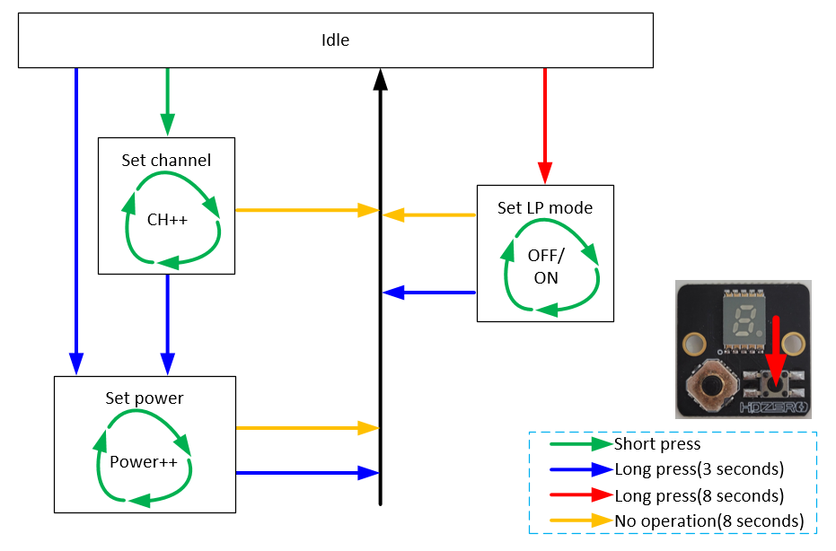
Stick Command
Before using stick command, make sure that fc uart is set correctly.
VTX Menu
All HDZero VTXes have the following settings for its RF power level management. These settings can be changed using the VTX menu.
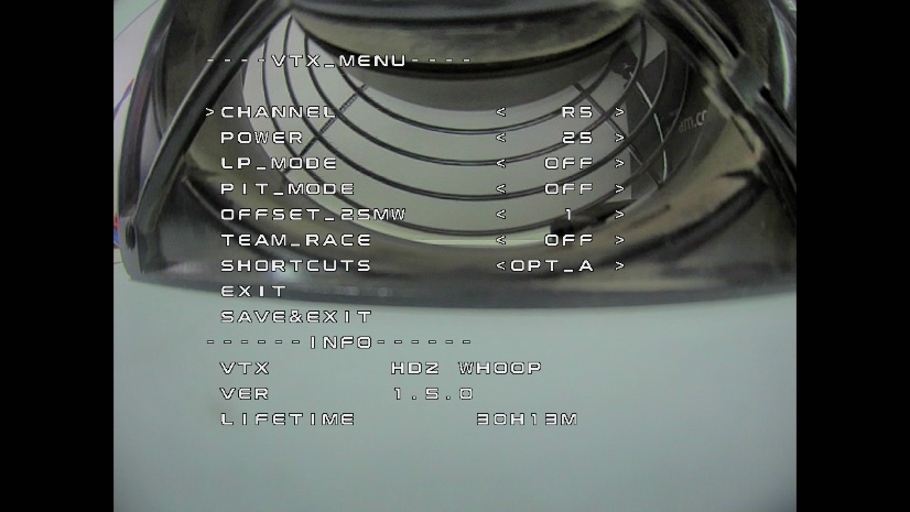
CHANNEL
- All VTXes support R1-R8, E1, F1, F2 and F4 channels. You will get an additional 8 channels L1-L8 if you unlock the lowband.
POWER
- The desired RF power level is selectable between 25mW, 200mW (and 500mW or MAX for certain VTXes). The actual RF power level depends on the following settings and FC status.
LP_MODE
- OFF: The output RF power will be set to POWER setting.
- ON: If PIT_MODE is OFF and the quad is disarmed, the RF power level will be forced to 25mW regardless of POWER setting.The output RF power will be set to POWER setting when quad is armed.
- 1ST: If PIT_MODE is OFF, the RF power level will be forced to 25mW regardless of POWER setting when QUAD is power on, The output RF power will be set to POWER setting when QUAD is armed.
- Note that after first arm, the vtx will not enter lp mode again until vbat power is reset.
PIT_MODE
- OFF: The output RF power will be set to POWER setting.
- P1MW: The output RF power will be 0.1mW (in order to not interfere with other pilots) in this mode. If the quad is armed, RF output power will be automatically set to the POWER within seconds.
- 0MW: There will be zero RF output in this mode. If quad is armed, RF output power will be automatically set to POWER within seconds.
- Note that after first arm, the vtx will not enter pit mode again until vbat power is reset.
OFFSET_25MW
- It is to fine tune the RF output power to be exactly 25mW. The range is [-10:10], and step size is about 0.3dB per step.
TEAM_RACE
- OFF: The RF power of VTXs after power-on is determined by other settings.
- MODE1: VTX RF remains off (0mW) after power-up, and exits 0mW under the following conditions: 1. Quad is armed. 2. Exit 0mw mode through stick command. 3. Configure VTX power to non-0mW through FC UART or SmartAudio. If the UART communication between VTX and FC is disconnected, VTX will turn off the RF until UART communication is restored and repower the VTX.
- MODE2: VTX RF remains off(0mW) after power-up, and exits 0mW under the following conditions: 1. Quad is armed. 2. Exit 0mw mode through stick command. 3. Configure VTX power to non-0mW through FC.
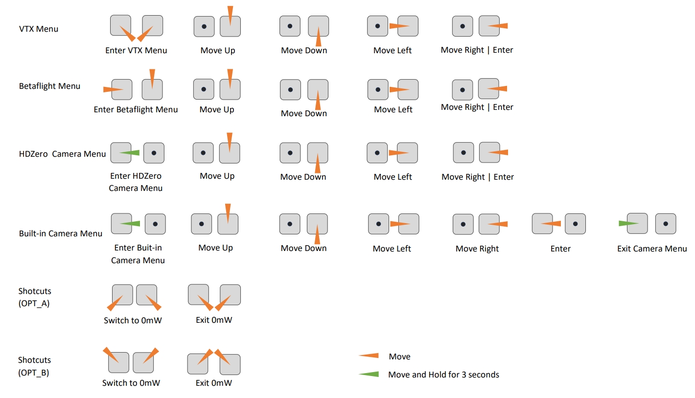
SHORTCUTS
- Two different stick commands are provided for switching or exiting 0mW. See the Stick Movement diagram for details.
Note
- HDZero VTX will still become hot even on P1mW mode. It is better to keep VTX on 0mW when it will be idle for a while. Though the receiver will not have live video on this mode, it will come back as soon as the quad is armed.
- Use sticks shortcut to enter 0mW, and to exit 0mW mode.
Smartaudio Protocol(Not recommend)
HDZero VTX can be controlled by FC using the TBS SmartAudio V2.1. In this case, the VTX will output RF power and channel commanded by FC directly. To avoid conflict, If SmartAudio is enabled, only OFFSET_25MW and SHORTCUTS are available in the VTX menu.
Note:
- HDZero VTX outputs 0.1mW when SmartAudio PIT mode is ON.
- HDZero VTX does not support SmartAudio out range PIT mode.
- When HDZero Race VTX boots up, it will automatically detect the existence of a valid SmartAudio link with FC within 10 seconds. If the link exists, FC will fully control race VTX’s RF output power and working frequency.
You don't need to set up the vtx table manually for betaflight, VTX will set it up automatically via uart port.
With SmartAudio, the user can change channel number and power level even when quad is in the air.
Unlock RF POWER Limit
HDZero Freestyle V1/V2 VTX is compliant with FCC 47 CFR 97.215(c). It is limited to 25mW/200mW out of the box, but it is capable of up to 1W if you have the required HAM radio license to use this power output. Download the special firmware from www.hd-zero.com/document to enable higher RF output modes.
Here are the steps:
- Download firmware Unlock_FreestyleVTX.zip.
- Unzip it to the root directory of SD Card.
- Use the VRX to flash this firmware to the VTX.
- Power on the VTX, BLUE LED will flash 3 times after it is done. This step unlocks VTX.
- Power the VTX off.
- Unzip normal VTX firmware to the root directory of SD Card.
- Use the VRX to flash this firmware to the VTX.
- The higher RF output options will now be available.
Please note once the VTX is unlocked, there is no need to unlock it again when there is newer firmware available.
Unlock Low band
The VTX low band needs to be unlocked before it can be used. Make sure your region allows low band before unlocking. To unlock low band for VTX:
Here are the steps:
- Download Unlock_Lowband.zip from www.hd-zero.com/document.
- Unzip and flash as firmware update to your VTX.
- Power on VTX, BLUE LED flashes 5 times and then goes out, unlock completed.
- Flash the latest release firmware to your VTX. When you switch channels in the VTX menu you will see additional channels from L1 to L8.